The Fab Academy 2014
Digital Fabrication Laboratory. Department of Architecture.
Institute of Technology. EPS-CEU San Pablo CEU University
Adolfo Gutiérrez Sánchez
Architect
The Fab Academy 2014 Digital Fabrication Laboratory. Department of Architecture. Institute of Technology. EPS-CEU San Pablo CEU University |
Adolfo Gutiérrez Sánchez Architect |
|||
| Home | Portfolio | Files | ||
| OUTPUT DEVICES |
|
 |
The assignment The assignment for this week was to add a output device to a microcontroller board I have already designed, and program it to do something. As my project needs a servo motor, I wanted to investigate something with it and to advance some of my project design. The servo that I have bought allows me to move until 4kg and the movement is allowed in the whole 360 degrees, so I will have to limitate it into 90 degrres only. |
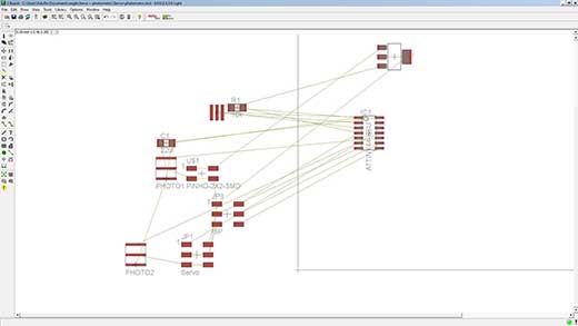
The board design As my project will need at least one servo (I am thinking of adding an extra one to the initial design), I will redesign the Servo Board to add two outputs with its VCC and GND pins in order to add the photometric board if needed.
|
||
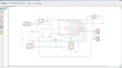
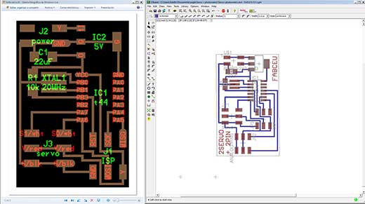
1. The first step is to redraw the board in Eagle, as I do not have the .sch and .brd files. 2. When I have redrawn the board, I have to add the two extra PIN outputs and connect them into two PINs of the Attiny44 microcontroller that are not used 3. Then we will have to connect all the wires in the schematic design, and to put all the values and the names of each of the wires. This step is important because it is very important to be very ordered in Eagle and to have all the components correctly assigned and drawn before changing into the Board Design. 4. When I have the Schematic Design, I can change into the Board Design and start drawing the paths that we will later mill on the Modela. This step is important to think it previously. Before starting to draw it is suitable to sketch the paths in a sheet of paper to save as much space as possible in order to make the board the small as possible. 5. Done that, we can export the files into the PNG files: - Traces.- to be milled with the 1/64" mill - Outline.- to be milled with the 1/32" mill |
 |
 |
 |
||
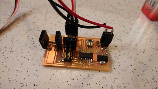 |
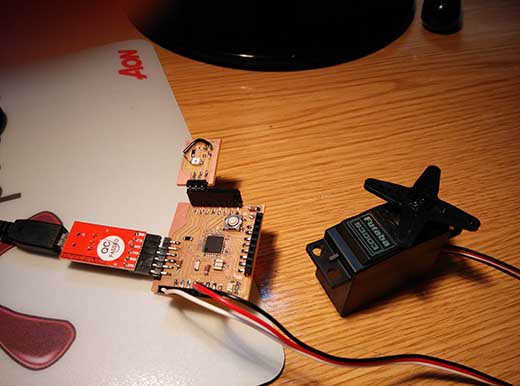
Assembly with my Servo Board Once we have milled the board, we should doublecheck all the connections. In this board, as we are going to connect a 9V battery directly into it, it is important to check and do not burn the microcontroller or our FabIsp. I had a few issues, and I had to invert the unweld and reweld back the microcontroller because I positioned it wrongly. |
|
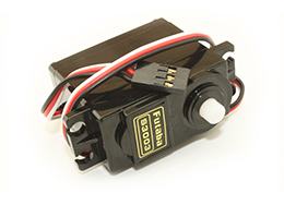
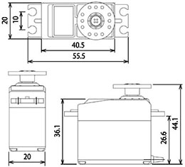
Arduino Programming. PWM Servo Connection Firstly, I tried to put into the board the Arduino Code that I had for my FabDuino, but I kept having some problems with the programming. The problem was that the Servo did not move in any of the programs that I put into the board. I looked for the problem in internet and, I found the problem in this link: making the Servo library work with the ATtiny85 sounds like a rather improbable proposition: If I'm not confusing things completely, the ATtiny85 just has 2 8-bit timers and no 16-bit timer, but the Servo-library relies on having a 16-bit timer available I realized, that I had to do something completely different with the programming, and not to program directly with Servo Library, but with PWM connections: // Servo with PWM connection_by Adolfo Gutierrez int pin = 7; } My Servo is a FUTABA S3003. I found some useful information (in spanish) where it says that my servo runs with 50Hz frequency and a length of a ratio between 0.3 and 2.3 ms. TO DO THINGS - I will try to connect the PHOTOMETRIC BOARD to move the Servo with this board. - Change the Arduino PWM code to do some different movements of the servo |
|
|
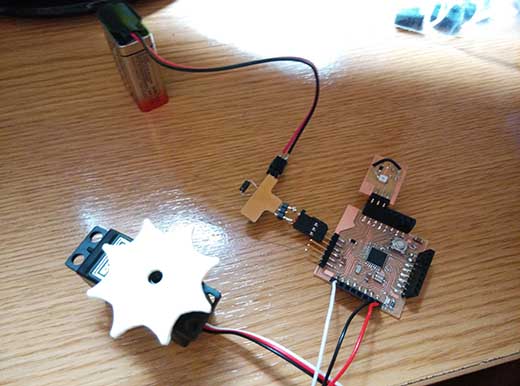
Assembly with my FabDuino The first step to controlthe servo with my FabDuino is to decide in whic pin is going to be connected. As far as I know, the servo has to be connected to a digital pin. The Servo has three cables: 5V, GND and the pin cable. Each of those ones have to be perfectly connected before connecting the FabDuino to the computer in order not to burn the USB of my computer. The board with the phototransistor that I did for the last week, is going to give me the data to move the servo. The phototransistor is going to read data from the light of the enviroment and it is going to move the servo into different positions. The only thing that I will need to control through my Arduino program is the degrees that I want to move with my servo. |
 |
|
|
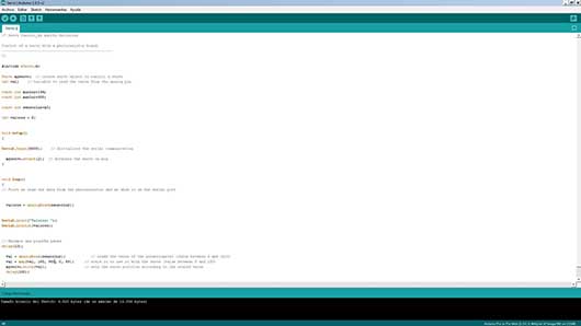
Programming with Arduino
The program that I wrote to the Arduino is pretty simple. Starting from the phototransistor code and viewing some examples, the servo only needs the values collected from the phototransistor and transform them into movement. For this example I controlled the values of the phototransistor from the range 0-1023 and transform into 0-89, so the servo only moves 90 degrees. /* Servo Control_by Adolfo Gutiérrez Control of a servo with a photoresistor board. #include <Servo.h> int valores = 0; void setup() Serial.begin(9600); myservo.attach(2); void loop() valores = analogRead(sensorLuz); Serial.print("Valores: "); val = analogRead(sensorLuz); }
|
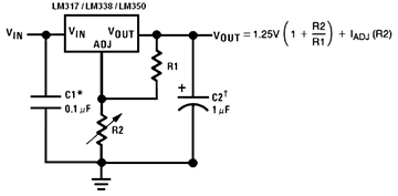
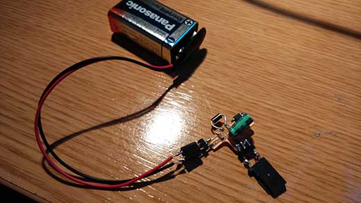
EXTRA ASSIGNMENT - Voltage Regulator I wanted to add an additional board to my FabDuino so it can be controlled alone and not connected to my computer, so I decided to design a board to attach a 9V battery into it, it will alow me to have an autonomous FabDuino. The first attempt was a complete disaster. This was an improvised board, and we did not have enogh components to assmbly the whole board, so we had to mix some SMD components with some TRUE HOLE components. The second attempt was much better. I added a DIODE to the board, in order that in case of putting the wires in the wrong position I wil not burn the microcontroller. The final result is very satisfactory. The servo and the photometric board work perfectly with the current of the 9V battery. The final assembly of the circuit will show as the following photo. In the video we can see the whole circuit working with the Voltage regulator. |
 |
 |
|
|